What Is Sand Casting?
Sand casting is a versatile molding process that uses compacted sand to form a cavity, into which molten iron is poured to produce near‑net‑shape castings suitable for a wide range of industrial applications.
Sand casting is a process in which a pattern of the desired part is pressed into sand to create a cavity, the cavity is filled with molten metal, and the sand mold is broken after solidification to retrieve the casting. It is widely used for gray iron, ductile iron, and alloyed cast irons because sand molds can handle high temperatures and are economical for both small batches and very large castings. Compared with processes like die casting or investment casting, sand casting has lower tooling cost and greater flexibility in size and geometry, but offers lower dimensional accuracy and rougher surface finish.
Key advantages include low tooling cost, suitability for very large parts, high flexibility in alloy choice, and the ability to handle complex internal passages using sand cores. Disadvantages include lower accuracy, thicker minimum wall sections, more cleaning and finishing work, and higher variation between parts if process control is weak. Typical applications range from machine tool bases, pumps, and valves to engine blocks, housings, and heavy machinery components in gray and ductile iron.
Both gray iron vs ductile iron grades are routinely poured in sand molds; browse our cast iron product range for typical components.
Essential terminology for iron sand casting
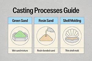
- Green sand: Moist clay‑bonded sand used in its “green” (unbaked) state for molding.
- Resin sand: Sand bonded with synthetic resins, cured to give higher strength and better surface finish.
- No‑bake: A resin‑bonded sand system cured at room temperature without baking; often used for large molds.
- Cope: The top half of a sand mold.
- Drag: The bottom half of a sand mold.
- Parting line: The interface plane where cope and drag meet.
- Gating system: Channels through which metal flows into the mold cavity.
- Sprue: Vertical channel that carries metal from the pouring basin into the runner.
- Runner: Horizontal channel that distributes metal from the sprue to one or more gates.
- Riser: Reservoir of molten metal that feeds the casting during solidification to compensate for shrinkage.
Step 1: Pattern Making
Pattern making creates the physical model of the casting used to form the mold cavity and includes allowances for shrinkage, machining, and draft. For iron castings, patterns are typically made slightly oversized by about 1–2% to compensate for solidification and cooling shrinkage. A draft angle (taper) of roughly 1–3 degrees on vertical surfaces helps with pattern withdrawal from the sand without damaging the mold. The choice of pattern material depends on intended production volume, dimensional tolerance requirements, and budget.
Wood Patterns
Wood patterns (e.g., hardwood, plywood) are common for prototypes and low‑volume production. They are relatively inexpensive and easy to modify, making them ideal when design changes are expected or annual quantities are modest. However, wood can warp or swell with humidity and is prone to wear, which reduces dimensional accuracy and repeatability over many molds. They are best for small‑to‑medium production runs where tooling cost must be kept low and product life cycles are short.
Metal Patterns
Metal patterns (typically aluminum or steel) are used for high‑volume or long‑running jobs that require improved accuracy and durability. They have excellent dimensional stability, can integrate features for automatic molding machines, and withstand thousands to hundreds of thousands of molding cycles. Their drawbacks are higher initial cost and longer lead time for manufacture, so they are only justified when production volumes are high enough to spread the tooling investment. Metal patterns are appropriate for automotive iron castings, pump and valve series, and other long‑term mass‑production projects.
Plastic Patterns
Plastic (or composite) patterns use materials like polyurethane, epoxy, or reinforced composites and bridge the gap between wood and metal. They offer better wear resistance and dimensional stability than wood and are lighter and often cheaper than metal, with moderate tooling cost and reasonable durability. Plastic patterns are particularly suitable for medium‑volume production where tolerances and repeatability matter, but volumes do not justify full metal tooling. They are also useful when weight is a concern, such as large patterns that must be handled manually or with light lifting equipment.
Step 2: Mold Preparation
Mold preparation converts the pattern into a sand mold capable of receiving molten iron. The three common processes for iron castings—green sand, resin sand, and no‑bake—differ primarily in the type of binder used and their balance of cost, accuracy, and productivity.

Green Sand Molding
Green sand molding uses silica sand, clay (typically bentonite), water, and sometimes small amounts of additives like sea coal. The sand is mixed, compacted around the pattern in the cope and drag, and then the pattern is withdrawn. Green sand offers the lowest cost per mold and is well suited to high‑volume production using automatic molding lines. Surface finish is moderate, and dimensional accuracy is adequate for many iron castings but not as high as resin systems. Green sand is used widely for automotive engine blocks, brake components, and medium‑sized housings where productivity and cost are key.
Resin Sand Molding
Resin sand molding uses sand coated with a thermosetting resin binder (such as phenolic or furan) that is cured by heat or chemical catalyst. This produces stronger molds with better dimensional accuracy and smoother surface finish than green sand. Resin sand molds are more expensive per mold due to binder cost and reclamation requirements, but they reduce machining allowances and can handle large, complex castings with good surface quality. This method is frequently used for medium‑to‑low volume production of complex iron castings such as pump bodies, valve housings, and machinery components where surface quality and dimensional stability are important.
No‑Bake (Air Set) Molding
No‑bake molding is a type of resin sand process where sand and resin are mixed and cured at room temperature without baking, usually using a liquid catalyst. The process is highly flexible and ideal for very large or heavy iron castings because the mold can be built in sections and assembled. Surface finish and dimensional accuracy are generally good, similar to or better than conventional resin sand, but the per‑mold cost is higher and cycle times are longer. No‑bake molds are commonly used for one‑off or low‑volume large castings such as machine tool beds, large frames, or heavy industrial components where tooling for high‑speed green sand lines would not be economical.
Step 3: Melting and Pouring
Iron for sand casting is melted in furnaces and then poured through a designed gating system into the mold. Proper control of metallurgy, temperature, and pouring practice is critical to avoid defects.
Furnace Types for Iron Melting
Common furnace types include cupola furnaces, coreless induction furnaces, and sometimes electric arc furnaces. Cupola furnaces use coke as fuel and are efficient for continuous high‑volume production but emit more pollution and are less flexible for frequent alloy changes. Coreless induction furnaces use electrical induction to melt metal, offer very good temperature and composition control, lower emissions, and are suitable for varying alloys and batch sizes, though their capital cost and electrical demand are higher. Electric arc or other auxiliary furnaces may be used in integrated steel plants or specialized foundries but are less common solely for iron castings.
Pouring Temperature and Technique
Typical pouring temperature ranges are about 1250–1450 °C for gray iron and 1350–1500 °C for ductile iron, with the higher range for ductile iron helping maintain nodularity and fill complex cavities. The gating system is designed so that the sprue delivers metal smoothly to the runner, which distributes flow to ingates while minimizing turbulence and air entrainment. Risers are located to feed hot spots and compensate for volumetric shrinkage during solidification. Common pouring defects include:
- Misruns: Metal solidifies before completely filling the cavity, often due to low temperature, thin sections, or poor gating; prevented by adequate superheat, correct section design, and well‑sized gates.
- Cold shuts: Two metal fronts meet without proper fusion, caused by turbulence or inadequate temperature; mitigated with better gating design and sufficient pouring temperature.
- Slag inclusions: Nonmetallic inclusions trapped in the casting, often due to poor slag separation or turbulent flow; reduced by effective slag removal, filters, and quiet gating.
Step 4: Cooling and Shakeout
After pouring, the mold and casting are left to cool until the iron solidifies and reaches a temperature suitable for shakeout. Cooling time depends on section thickness, casting mass, and mold material; small iron castings may be shaken out in less than an hour, whereas large, thick‑section castings may require many hours or even overnight cooling. The cooling rate strongly influences microstructure: in gray iron, faster cooling promotes finer pearlite and can increase strength, while in ductile iron, cooling rate affects nodule count, matrix structure (ferritic vs pearlitic), and resulting mechanical properties.
Shakeout is the process of breaking the sand mold to release the solidified casting, using mechanical shakeout equipment for high‑volume production or manual methods for large or special castings. Defects related to cooling include shrinkage porosity, which occurs in hot spots that are not adequately fed by risers; and hot tears, which are cracks formed by restrained contraction when sections are locked by the mold. Proper riser design, chills to control solidification paths, and correct mold rigidity help prevent these problems. Controlled cooling rates and heat‑treatment planning also reduce internal stresses and cracking risk.
Step 5: Cleaning and Finishing
After shakeout, castings undergo cleaning and finishing to remove sand, gates, and risers and to achieve the specified surface quality. The sequence typically includes:
- Fettling: Rough removal of gating, risers, and flash using oxy‑fuel cutting, saws, or large grinders.
- Runner and riser removal: More precise cutting or grinding down to near final contour.
- Grinding: Smoothing of cut‑off areas and removal of minor surface imperfections, using hand grinders or automated grinding cells.
- Shot blasting: Abrasive cleaning using steel shot or grit to remove residual sand, scale, and rust, producing a relatively uniform matte surface.
Depending on requirements, iron castings may receive heat treatment such as stress‑relief (to reduce residual stresses), annealing (to soften and increase ductility), or normalizing (to refine pearlite and improve strength and uniformity). Typical surface finish after shot blasting is adequate for most industrial parts, though critical surfaces are usually machined. Final inspection before shipping includes dimensional checks, surface defect evaluation, and verification that machining allowances, casting integrity, and marking/traceability requirements are met.
For finishing and logistics support, see custom iron casting services across machining and delivery.
Quality Checks During Each Stage
Quality control in sand casting begins at pattern making and continues through final inspection. During pattern making, dimensional accuracy and allowance (shrinkage, machining, draft) are verified against drawings, and critical features are checked using gauges or CMMs for high‑precision projects. In mold preparation, sand properties such as moisture, compactability, permeability, and strength are monitored regularly to ensure consistent mold quality and to avoid defects like sand inclusion or poor surface finish.
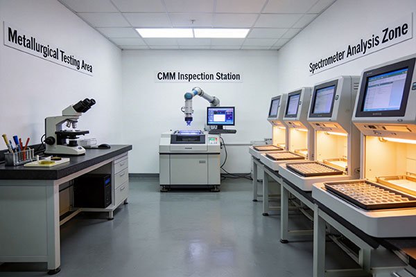
In melting and pouring, chemical composition is controlled via spectrometer or other rapid analysis methods; samples are taken frequently from the melt to ensure carbon, silicon, and alloy content remain within specified ranges for gray or ductile iron. Mechanical property testing (tensile, hardness, sometimes impact) is typically carried out on separately cast test bars according to relevant ASTM or ISO standards to confirm that grade requirements are met. Non‑destructive testing methods such as ultrasonic testing (to detect internal defects in thick sections), magnetic particle testing (for surface and near‑surface cracks in ferromagnetic iron), and dye penetrant testing (for surface cracks on machined areas) are used as needed, especially for safety‑critical components. Acceptance criteria are defined by drawing or standard and commonly limit defect size, type, and location to ensure fitness for purpose.
Sand Casting vs Other Methods
| Process | Surface finish | Dimensional accuracy | Tooling cost | Per‑part cost | Volume suitability | Min wall thickness | Typical lead time |
|---|---|---|---|---|---|---|---|
| Sand casting | Fair to moderate | Moderate | Low | Low–moderate | Low to very high, very large parts | Relatively thick | Short–moderate |
| Investment casting | Excellent | High | Moderate–high | High (small parts) | Low–medium, small/complex | Very thin possible | Moderate–long |
| Die casting | Very good | High | Very high | Low at high volume | High‑volume, smaller parts | Thin sections | Long for tooling |
| Permanent mold | Good | Higher than sand | High | Moderate | Medium–high, moderate size | Thinner than sand | Moderate |
Sand casting remains preferred for iron when parts are large or heavy, when tooling budgets are constrained, when alloys are not suitable for die casting, or when flexibility in design changes and low‑to‑medium volumes are important. It is particularly advantageous for heavy gray and ductile iron components such as housings, bases, and structural castings that cannot be produced economically by other methods.
FAQ
What is sand casting and how does it work for iron castings?
Sand casting for iron uses a pattern to form a cavity in compacted sand, which is then filled with molten gray or ductile iron and allowed to solidify before the sand is broken away and the casting is cleaned and finished. The process involves pattern making, sand mold preparation, melting and pouring, cooling and shakeout, and finally cleaning, machining, and inspection. It is suitable for a wide range of sizes and shapes, from small fittings to very large machine bases, and offers low tooling cost and good material flexibility compared with other casting methods, at the expense of rougher surface finish and lower dimensional accuracy.
Typical timeline for iron sand castings
The timeline for sand casting iron parts depends heavily on part size, complexity, and production setup. Pattern design and manufacture may take from a few days to several weeks depending on pattern material and complexity. For small castings, once tooling exists, the cycle from molding to finished casting may be as short as 1–3 days, including cooling, cleaning, and basic finishing. Medium‑sized castings might require several days for mold preparation, pouring, cooling (often overnight), and processing, so total time from mold to finished casting is commonly about 3–7 days. Large iron castings can take much longer; cooling and handling may add days, so a complete cycle from mold preparation through finishing and inspection may extend to 1–3 weeks or more, depending on foundry load and any required heat treatment.
Most common defects and prevention
- Common defects in iron sand castings include:
- Shrinkage porosity – caused by insufficient feeding of hot sections during solidification; prevented by proper riser design, use of chills, and optimized solidification paths.
- Gas porosity – caused by moisture, binder decomposition, or gas entrapment; reduced by controlling sand moisture, venting molds, and proper melt degassing and slag removal.
- Sand inclusion – loose or eroded sand entering the cavity, often due to weak mold strength or high turbulence; minimized through correct sand properties, mold design, and gentle gating.
- Cold shuts/misruns – incomplete fusion or filling caused by low metal temperature, thin sections, or poor gating; improved by adequate superheat, proper pouring speed, and suitable section thickness.
- Hot tears – cracks formed during constrained contraction at high temperature; prevented by uniform section design, generous fillets, proper mold collapsibility, and careful placement of cores and chills.
Green sand vs resin sand molding: which to choose?
Green sand molding is usually lower cost per mold and highly productive, making it ideal for high‑volume iron castings where moderate surface finish and dimensional accuracy are acceptable. Resin sand molding costs more per mold but delivers better surface finish and higher dimensional stability, reduces machining stock, and is more suitable for complex or medium‑to‑large castings at low to medium volumes. For a project prioritizing minimum cost and high annual quantities of robust industrial parts, green sand is often the best choice; for more complex shapes, tighter tolerances, or lower volumes where tooling flexibility and surface quality are important, resin sand or no‑bake molding is typically preferred.